
A miniature collection can bring together a surprising range of design and manufacturing problems. The models need enough room for their height, poses and projecting details. Their trays need to be easy to remove, while the case needs a layout that works for different sizes of miniature. This Warhammer 40k storage and transport project brought those requirements into one build, using CAD design, 3D scanning, CNC routing, filament 3D printing and resin 3D printing.
Designing around the miniature collection
I wanted a modular storage and transport system that worked with magnetized models without the cost and compromises of the commercially available cases I had considered. Readily available dollar-store trays became the starting point. Their dimensions set the tray interface, and removable trays made it possible to take part of the collection out without unpacking the whole case.
Resin printing: the collection the case needed to hold
I also used a resin printer to print the 40k models. That made resin printing part of the wider project: the case was being designed around a real collection of printed miniatures. The photos show why a single fixed shelf spacing would be limiting. Smaller figures can share a shallow level, while larger models need considerably more space above their bases.
3D scanning: bringing the real model into the design
To check that the case would be appropriately sized, I used the 3D scanner to scan a model as a reference. Tray measurements describe the support surface, but they do not describe the shape standing on it. A scanned reference brought the miniature’s physical size and form into the design process so the case could be considered around the model, rather than around tray dimensions alone.
The scan served a different purpose from the resin printing. Scanning supplied a reference for checking the storage space; resin printing produced the miniatures that would use it. Together, they connected the digital design work to the actual objects the case needed to accommodate.
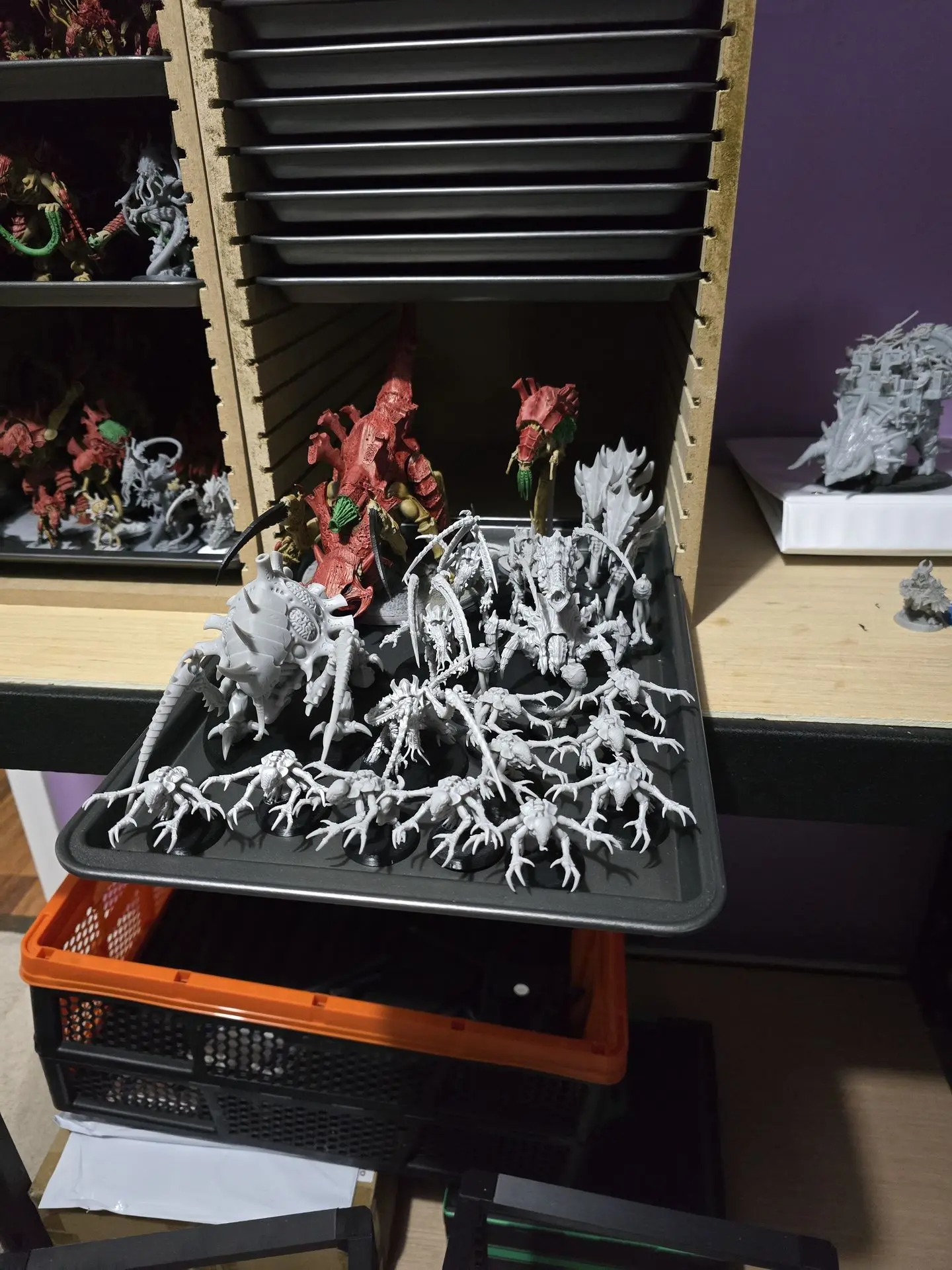
Resin-printed miniatures on a removable tray, with taller models and closely stacked trays behind them.
FreeCAD: designing the case and its manufacturing features
I designed the project in FreeCAD around half-inch MDF and the trays I intended to use. The design included the case panels, the joints that let the panels slot together, and the internal grooves that support removable trays at different heights. The tray dimensions were checked against the physical trays during the design stage.
The grooves are central to the layout. Instead of committing every tray to one shelf height, the repeated positions let the space between levels change to suit the collection. The photographs show cases with closely stacked empty trays as well as wider spacing for larger miniatures. The useful result comes from designing the tray positions, case geometry and assembly joints as parts of the same system.
CNC routing: turning the design into the MDF body
The large, flat case panels were cut on the CNC machine. The cutting layout was reviewed and a dry run completed before machining the material. The CNC then cut the panel outlines and the repeated tray grooves, translating the design’s assembly and storage features into the physical parts.
After cutting, I cleaned up the edges and checked the parts together. The case was assembled with wood glue and brad nails, then the glue was allowed to cure for 24 hours before checking the trays in their slots. The build photos show the cut sheet, an early tray-fit check and the case held square with assembly clamps.
This stage also provided feedback that CAD alone could not settle. The panels could fit together for assembly while individual tray clearances still needed adjustment. Checking the real trays in the machined grooves made those differences visible and gave the next revision a specific fit problem to address.
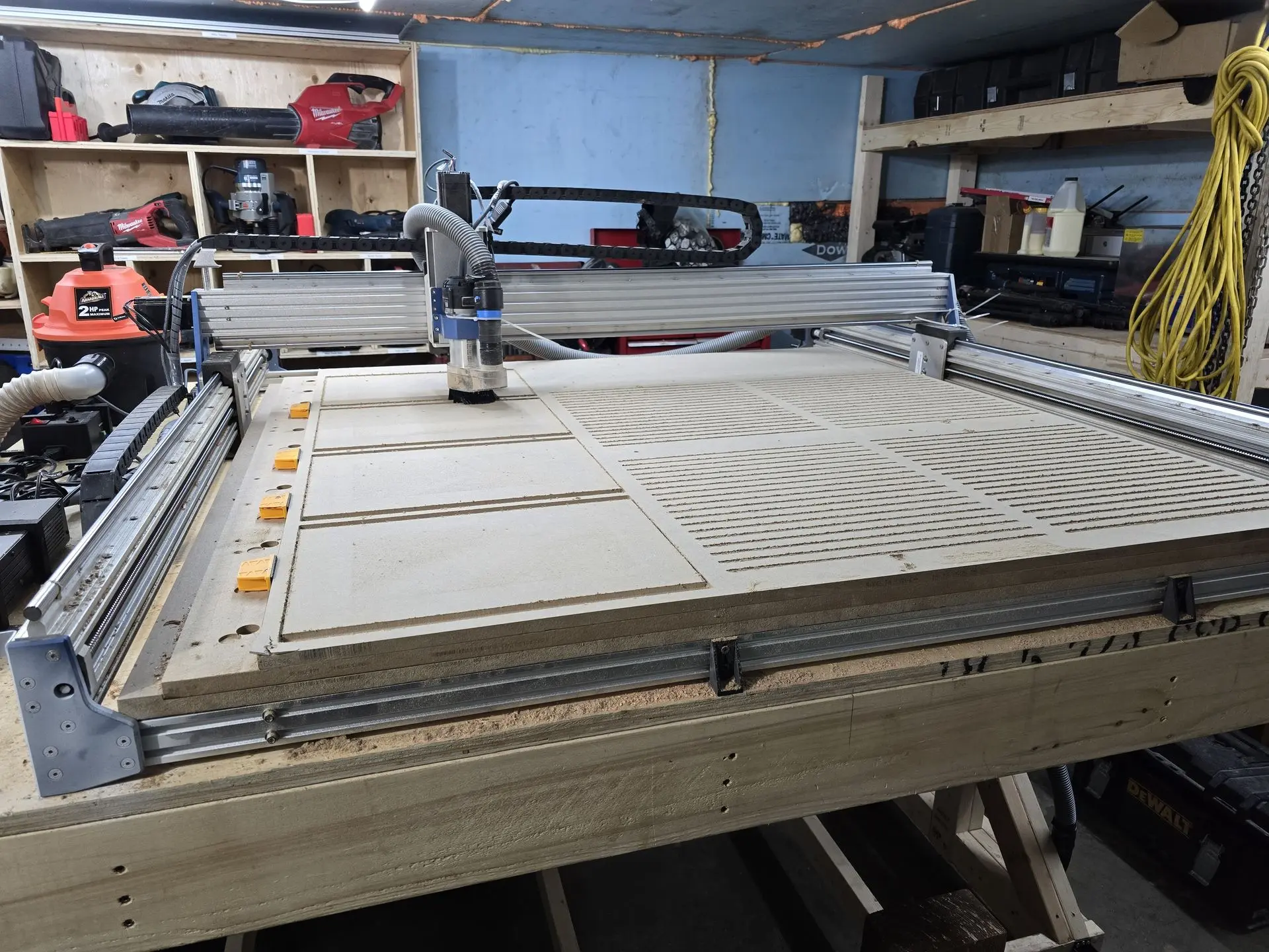
CNC-cut MDF panels and repeated tray grooves on the machine bed.
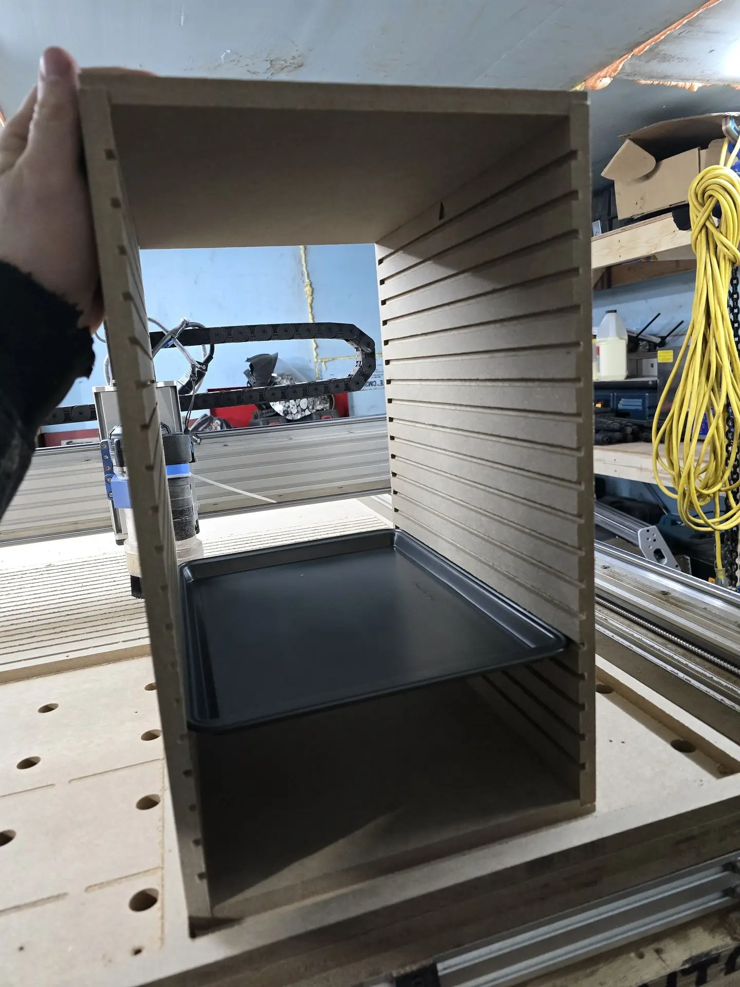
An early fit check with a tray between the machined side panels.
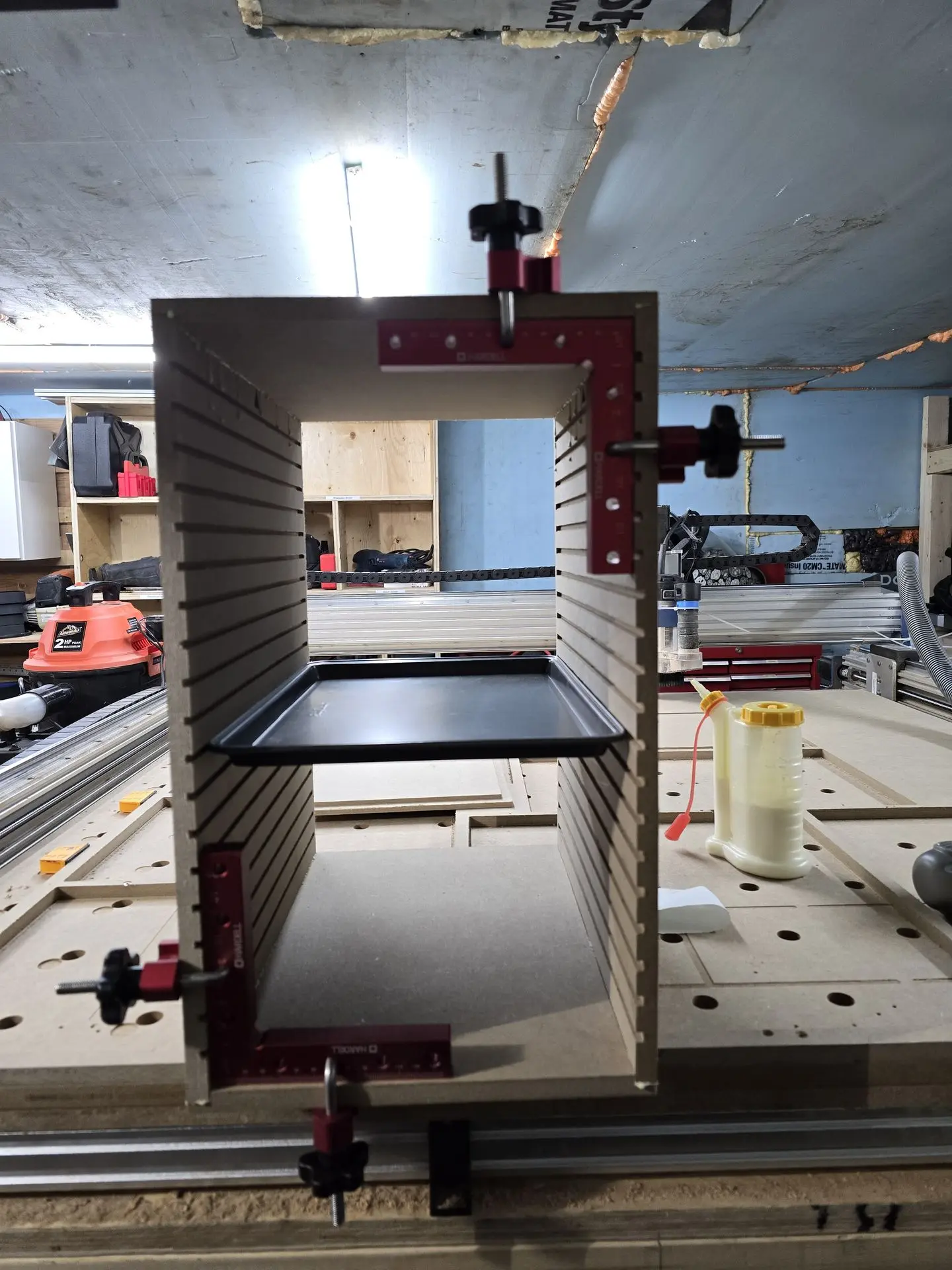
The MDF case held square with assembly clamps.
Filament 3D printing: custom hardware for the case
The CNC-cut body was complemented by custom 3D-printed components, including the carry handle, its internal washer plate and the corner protectors. I designed the handle in FreeCAD and used the 3D printer to make the handles. The CAD view and installed photographs show the same progression from a shaped digital part to hardware fitted to the case.
The handle mounts through the top panel. Inside the case, a printed washer plate sits beneath the fasteners, while printed corner pieces fit around the outer edges. These smaller components gave the project a second manufacturing method alongside the CNC-built MDF body.
That combination is a useful part of the case study. The panel geometry went to the CNC, and the shaped hardware went to the 3D printer. Both were designed to fit the same assembly, so the case body and its accessories could be developed together rather than treated as unrelated projects.
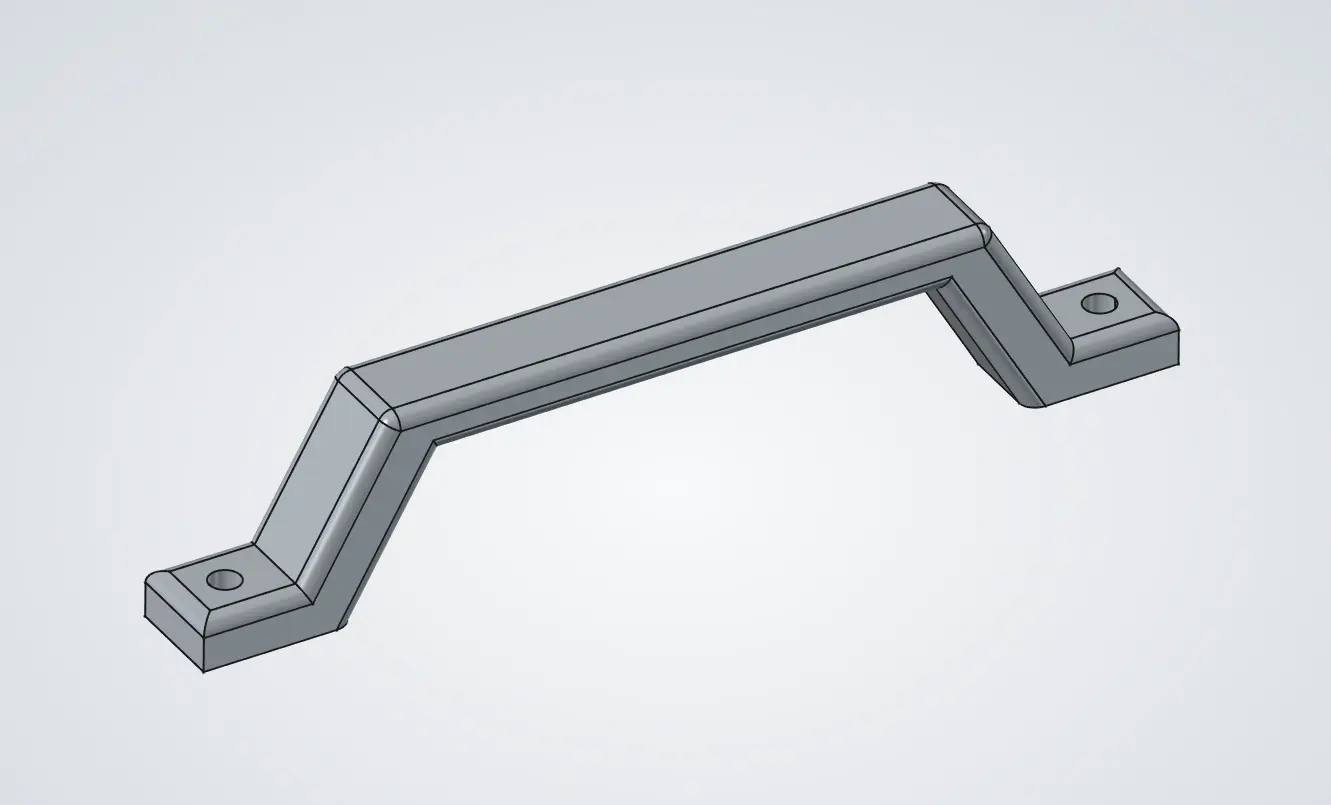
The custom carry handle modeled in FreeCAD before printing.
The result: one project connecting five capabilities
The assembled cases provide removable tray storage for the miniature collection, with different tray spacings visible across the builds. The models, trays, machined body and printed hardware are all shown together in the project photos. The removable-tray view demonstrates the storage arrangement, while the later handle and washer-plate photos show the added case hardware.
Each capability contributed a different piece of the solution. Resin printing produced the miniatures. 3D scanning supplied a physical model reference for sizing. FreeCAD brought the case, tray interface and hardware into a digital design. CNC routing produced the MDF panels and grooves. Filament 3D printing supplied the custom handles and other case components.
The value of bringing these services together is the connection between the steps. The objects being stored informed the dimensions; the design incorporated the manufacturing method; and assembly checks informed the next design revision. It is a practical example of how Q3D Solutions can combine design, scanning and several manufacturing processes around one problem.
What the next revision changes
The next revision focuses on tray-slot tolerances and side-to-side clearance so insertion and retention are more consistent. Some initial slots were tight, while other clearances allowed more sideways movement than intended. The manufacturing design also has predefined carry-handle holes recorded as a planned refinement.
These fit refinements will not visibly change the case shown here. The current build is shared as the case study, with the revised tolerances still to be completed and retested. The photographs document the actual builds and fitted hardware, while the remaining revision work stays separate from what has already been made.
The cases, trays and fitted hardware
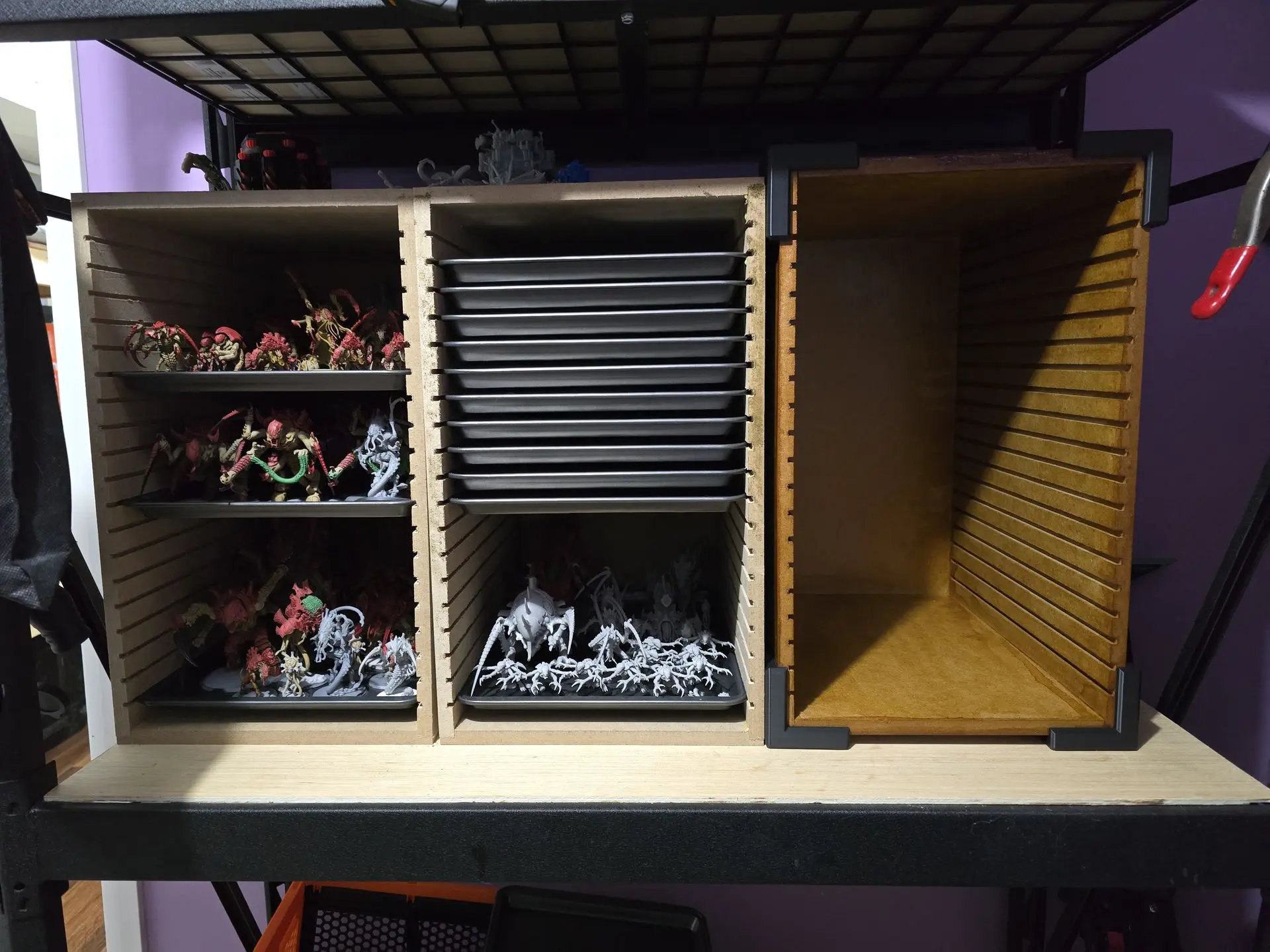
Cases arranged with different tray spacings for the miniature collection.
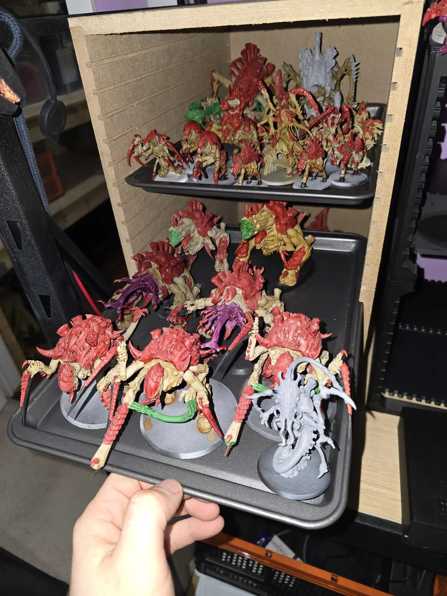
Removable trays holding miniatures in the CNC-cut MDF case.
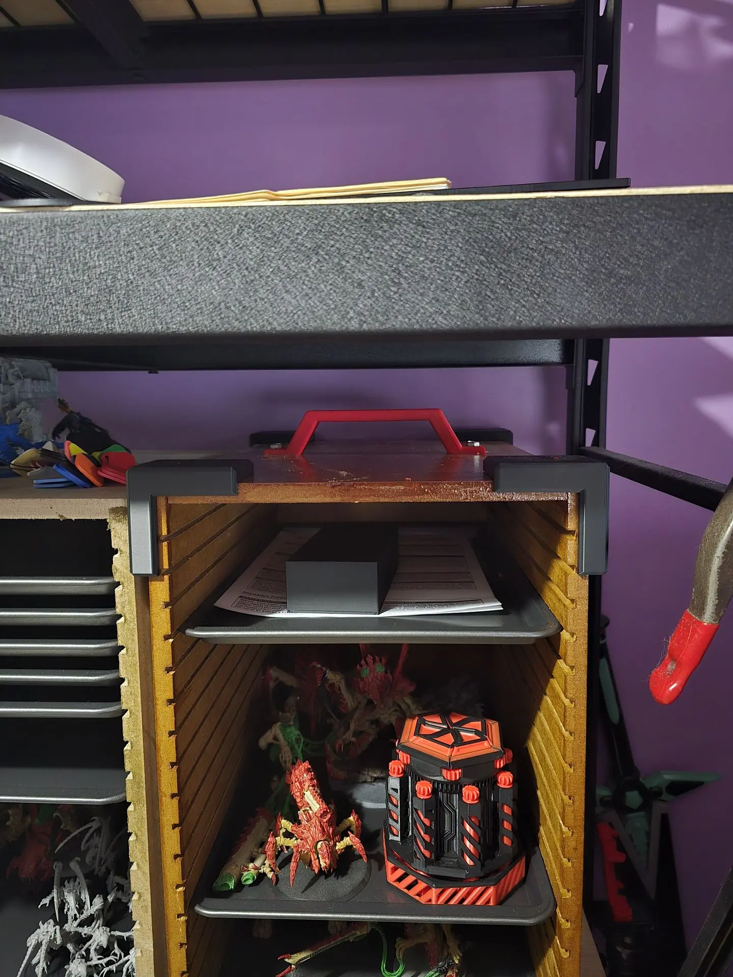
The assembled case with its 3D-printed carry handle and corner protectors.
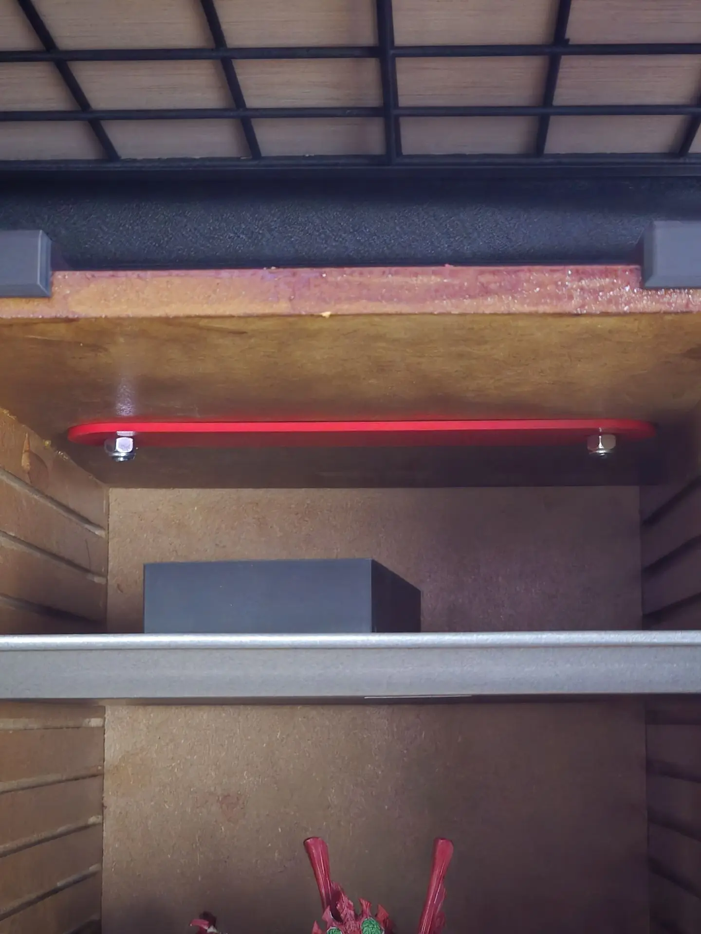
The internal washer plate securing the carry handle through the top panel.
For projects that combine design, scanning and manufacturing, explore our services or contact us to discuss your requirements.